

GoodTech MFG Group Limited
Handson Zingying Plastic Metal Ltd
Handson Zingying Plastic Metal Ltd
Views: 724 Author: Site Editor Publish Time: 2025-10-11 Origin: Site
Think of an injection mold not as a simple block of steel, but as a complex, custom-built 3D puzzle. Each precisely engineered piece has a critical job to do. For designers and engineers, understanding how this puzzle fits together is the secret to creating plastic parts that are not only beautiful but also highly manufacturable and cost-effective.
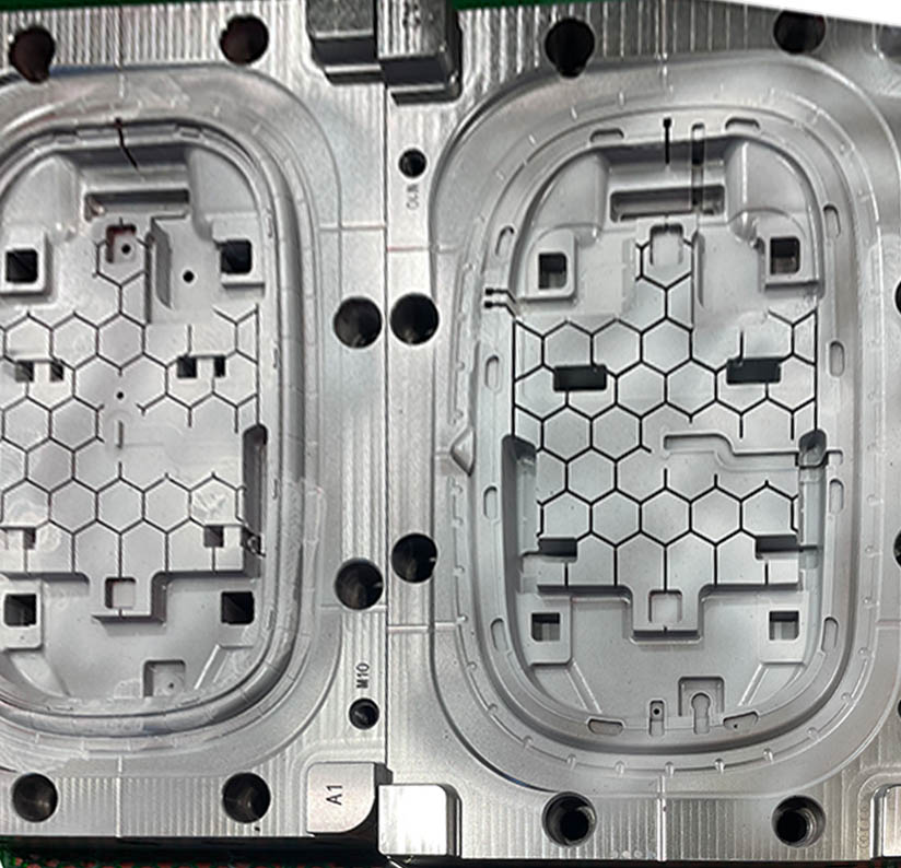
An injection mold is a sophisticated manufacturing tool used to mass-produce plastic parts. It consists of two primary halves—the A-side (cavity) and the B-side (core)—that securely close to form the part's shape. Housed within these halves are multiple integrated systems for feeding molten plastic, managing temperature, venting air, and ejecting the finished, solid part. This intricate structure ensures every single part is produced with incredible precision and repeatability.
But what are all those plates, pins, and channels really doing? In this guide, we'll take you on a complete tour inside a typical injection mold. We will break down each system and its core components, revealing exactly how the tool’s structure works and, more importantly, how it directly influences the design decisions you make for your product.
Every injection mold, regardless of its complexity, is built around one fundamental principle: it is a tool made of two distinct halves that press together. These halves meet to form the empty space—the mold cavity—that will be filled with molten plastic. Understanding the role of each half is the first step to understanding the entire mold structure.
The A-side is the half of the mold that mounts to the stationary platen of the injection molding machine. This is the side where the plastic enters the mold through the sprue bushing. Because it doesn't move, it's often called the "fixed half." Typically, the A-side forms the exterior cosmetic surface of the final part, which is why it's also commonly referred to as the cavity half.
The B-side is the half of the mold that mounts to the moving platen of the machine. When the molding cycle is complete, this is the half that retracts to open the mold. The B-side usually contains the core of the mold, which forms the internal features of the plastic part. Crucially, the B-side also houses the entire ejection system, which is responsible for pushing the finished part out of the mold. For this reason, it's also known as the core half or "ejector half."
The parting line is the precise surface where the A-side and B-side meet when the mold is closed. It's the perimeter that separates the two halves. The location of the parting line is one of the most critical decisions in mold design, as it affects the final appearance of the part, the complexity of the tool, and how the part is ejected. A faint line, often visible on finished plastic parts, marks this junction.
In simple terms, the cavity is the concave part of the mold (usually in the A-side) that forms the outer surface of the plastic part—like a hollow bowl. The core is the convex part of the mold (usually in the B-side) that forms the inner surface of the part—like the mound you'd press into the bowl. When the mold closes, the space between the core and the cavity is what becomes your finished plastic component.
Now that we understand the two halves, let's look inside. A mold isn't just a cavity and a core; it's an assembly of several interconnected systems, each with a specific job. For a mold to function correctly, all these systems must work in perfect harmony. We will explore each one in detail.
Part 1: The Guiding System - Ensuring Perfect Alignment
The guiding system acts as the mold's skeleton, ensuring the A-side and B-side align perfectly every time the mold closes. Without it, the two halves would misalign, leading to catastrophic failure.
The primary components of this system are guide pins (or leader pins) and bushings. Guide pins are hardened steel posts, typically located on one half of the mold, that slide into precisely machined holes called bushings on the other half. This simple but critical mechanism ensures that the core and cavity are perfectly centered as the mold closes under high pressure.
Even a slight misalignment of a fraction of a millimeter can be disastrous. The immense pressure of the closing mold could cause the core and cavity to crash into each other, damaging the highly polished and textured surfaces. This would result in:
Uneven wall thickness on the final part.
Flash, where plastic seeps out of the intended cavity.
Permanent damage to the expensive, custom-machined mold surfaces, requiring costly repairs.
For very large or high-precision molds, guide pins alone may not be enough. In these cases, designers add interlocks. These are tapered blocks of steel, one male and one female, mounted on the parting line. As the mold closes, they engage and lock the two halves together with extreme rigidity, preventing any shifting during the high-pressure injection phase. This ensures maximum stability and part quality.
The feeding system is the network of channels that transports molten plastic from the injection molding machine's nozzle to the part cavity. The design of this system is crucial for ensuring the cavity fills completely and uniformly, directly impacting the final part's quality and cosmetic appearance.
The journey begins where the nozzle of the molding machine presses against the sprue bushing on the A-side of the mold. This bushing has a tapered hole, called the sprue, which acts as the main entrance for the plastic. It's designed to receive the high-pressure flow and channel it into the rest of the mold.
After the sprue, the plastic flows into the runners. These are channels machined into the mold surface that distribute the molten material from the single sprue to the various entry points of the part cavity. In a multi-cavity mold, the runner system branches out to feed all the cavities simultaneously. The shape and size of the runners are carefully designed to maintain pressure and temperature, ensuring all cavities fill at the same rate.
The gate is the final, narrow opening through which the plastic enters the actual part cavity. The gate's location, size, and type are critical design decisions. It influences how the part fills, where weld lines appear, and how easily the finished part and runner system can be separated. After molding, the gate leaves a small remnant or "vestige" on the part that may need to be trimmed.
At the start of each injection shot, the plastic at the very tip of the machine's nozzle cools down slightly. This semi-solidified "cold slug" can clog the gate or cause cosmetic defects if it enters the cavity. To prevent this, a cold slug well is often designed at the end of the sprue or runner. It's a small pocket that traps this colder material, allowing the hotter, more fluid plastic behind it to flow smoothly into the part.
If the mold base is the skeleton, the molding system is the heart. This system comprises the highly precise components that directly shape the molten plastic into your final part. It's where the most complex and custom machining work takes place, and it's what ultimately defines the part's geometry and features.
As we've discussed, the cavity and core are the main shape-forming elements. The cavity is the female half that typically forms the outer, cosmetic surfaces, while the core is the male half that forms the inner features. The steel used for these components is of the highest quality, often hardened and highly polished or textured to create the desired surface finish on the part.
A simple part can be ejected directly as the mold opens. But what if your design includes a feature like a side hole, a snap-fit clip, or a recessed groove? These features are called undercuts because they prevent the part from being pulled straight out of the mold. To solve this, mold designers use moving components called "actions."
Slides (or Sliders): These are blocks of steel that move perpendicular to the mold opening direction. Before the part is ejected, the slide is pulled away, clearing the undercut feature and creating a path for ejection.
Lifters: These are components that move at an angle as the ejector system pushes forward. They are used to form undercuts on the inside of a part, lifting up and away from the feature as the part is ejected.
Instead of machining the entire core or cavity from a single, massive block of steel, toolmakers often use inserts. These are smaller, separate blocks of steel that are fitted into pockets within the larger mold base. Inserts are used for several strategic reasons:
Ease of Manufacturing: It is far easier to machine a small, complex insert than to work inside a large, deep mold block.
Maintenance & Repair: If a small feature wears out or is damaged, only the insert needs to be replaced, not the entire mold half.
Different Materials: A high-wear area, like a gate, can be made from a harder, more durable steel insert while the rest of the mold is made from a standard tool steel.
Improved Cooling: Inserts can incorporate dedicated cooling channels to better manage heat in hard-to-reach areas of a part.
Two invisible but essential forces in injection molding are heat and air. The cooling and venting systems are designed to control them. Proper cooling ensures a fast cycle time and a stable part, while proper venting allows trapped air to escape, preventing critical molding defects.
After the molten plastic is injected, it must cool and solidify into its final shape. This cooling phase is typically the longest part of the entire injection molding cycle. To speed this up, a network of cooling channels is drilled through the mold plates. A temperature-controlled fluid (usually water) is constantly circulated through these channels to draw heat away from the steel and the plastic part. A well-designed cooling layout is uniform and efficient, leading to shorter cycle times and dimensionally stable parts with minimal warping.
When molten plastic rushes into the mold cavity, it displaces the air that's already there. If this air has no way to escape, it gets compressed and trapped by the incoming plastic. This trapped, super-heated air can cause a range of serious defects, including:
Short Shots: The part doesn't fill completely because the trapped air physically blocks the plastic flow.
Burn Marks: The compressed air heats up so much that it scorches the plastic, leaving black or brown marks on the part.
Weld Lines: The air can prevent two merging plastic fronts from fusing properly, creating weak, visible lines.
To prevent this, tiny channels called vents are machined into the parting line. These vents are very shallow—typically only 0.01 to 0.03 mm deep—just large enough to let air escape, but too small for the viscous plastic to flow through.
Effective part design must account for cooling and venting. For example, a designer should aim for uniform wall thickness to promote even cooling and prevent warping. They must also be aware that vents are needed at the very last point the plastic will fill, so part geometry can influence where vents can and cannot be placed.
Once the part has cooled and solidified, it must be removed from the mold. This is the job of the ejection system. As the plastic cools, it shrinks and grips tightly onto the core half (B-side) of the mold. The ejection system provides a mechanical force to push the part off the core, allowing it to be removed.
Housed within the B-side of the mold is the ejector assembly. It consists of two main plates: the ejector plate and the ejector retainer plate. All the various ejector pins are mounted to this assembly. When the molding machine's hydraulic ejector rod pushes this entire assembly forward, all the pins move in unison to push the part out of the cavity.
Ejector pins are the most common and cost-effective way to eject a part. They are hardened steel pins that pass through the B-side of the mold and press against the finished part. When the ejector assembly moves forward, the pins protrude from the mold face and push the part off the core. These pins leave small, circular marks (ejector pin marks) on the part, which should ideally be placed on non-cosmetic surfaces.
While pins are common, sometimes a different approach is needed. Other methods include:
Ejector Sleeves: These are hollow pins used to eject round features like bosses or standoffs. The sleeve pushes on the rim of the boss, providing even pressure and avoiding the need for a pin mark on top.
Ejector Blades: These are rectangular pins used to eject thin, tall ribs where a round pin would not fit or provide enough surface area.
Stripper Plates: For delicate or thin-walled parts, a stripper plate can be used. This is a plate that contacts the entire edge of the part and pushes it off evenly, distributing the ejection force and preventing warping or damage.
After the part is ejected, the entire ejector plate assembly must be pulled back to its starting position before the mold closes for the next cycle. This is the job of the return pins. As the mold closes, these pins make contact with the A-side face, pushing the ejector system back into its retracted position, ready for the next shot.
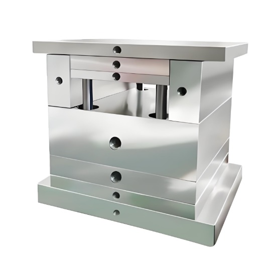
If the core and cavity are the heart of the mold, the mold base is the entire skeleton. It is a pre-manufactured assembly of steel plates, pins, and components that acts as the foundational structure for the custom-machined core, cavity, and all other systems. Using a standardized mold base dramatically speeds up the tool-making process.
Mold bases are typically purchased from specialized suppliers like DME or Hasco. They come in a vast range of standard sizes and configurations. This allows mold makers like us to focus our time and expertise on the most critical, custom parts of the tool—the core, cavity, and actions—rather than building the entire structure from scratch.
A standard mold base is a sandwich of several steel plates, each with a specific name and function. Here are the most important ones:
| Component Name | Primary Function |
|---|---|
| Top Clamping Plate | Mounts the A-side of the mold to the machine's fixed platen. |
| A-Plate (Cavity Plate) | Houses the cavity half of the mold and the runner system. |
| B-Plate (Core Plate) | Houses the core half of the mold. |
| Support Plate | Supports the B-Plate against the immense pressure of injection. |
| Spacer Blocks | Create a gap between the B-Plate and the bottom clamping plate, providing space for the ejector system to move. |
| Ejector Box | The space created by the spacer blocks, which contains the ejector assembly. |
| Ejector Plates | The moving assembly that holds the ejector pins and is pushed forward to eject the part. |
| Bottom Clamping Plate | Mounts the B-side of the mold to the machine's moving platen. |
Understanding a mold's structure isn't just for toolmakers; it's essential for product designers. A good plastic part is designed with the mold in mind. By anticipating how these systems work, you can create parts that are easier to manufacture, more cost-effective, and higher in quality. This is the core principle of Design for Manufacturability (DFM).
Because the ejection system pushes the part off the core, the walls of your part cannot be perfectly vertical (90 degrees). They need a slight taper, known as a draft angle, to allow for a clean release. Without draft, the part would scrape against the mold wall, causing drag marks and potentially getting stuck, halting production.
As we learned, features like side holes require complex actions like slides or lifters. These mechanisms add significant cost and complexity to a mold. As a designer, you should always ask: "Is this undercut feature absolutely necessary?" If it can be designed out without compromising function, you will save significant time and money on tooling.
The gate, part of the feeding system, will always leave a small mark on your part. For cosmetic components, it's crucial to consider where this mark will be. Designers can and should specify "gate-free" zones on their drawings to ensure the vestige is placed on a non-visible surface. Gate location also influences plastic flow, which can affect the location of weld lines and the overall strength of the part.
The cooling system works best when it can draw heat away from the part uniformly. If your part has a very thick section next to a very thin one, the thick section will take much longer to cool. This differential cooling is a primary cause of part warping and sink marks. The golden rule of DFM is to maintain a uniform wall thickness throughout your part whenever possible.
A standard 2-plate mold has one parting line and ejects the part and runner system together. A 3-plate mold has two parting lines, which allows the runner system to be automatically separated from the part and ejected separately. This is useful for certain gating types, like pin-point gates.
A hot runner system replaces the conventional cold runner with a heated manifold and nozzles. This keeps the plastic molten all the way to the gate, eliminating the runner scrap. It adds complexity, requiring channels for heating elements and wiring, but it reduces material waste and can shorten cycle times.
"Actions" is a general term for moving components within the mold that are used to form undercuts. The most common types of actions are slides (which move horizontally) and lifters (which move at an angle). They add complexity and cost but are essential for molding complex geometries.
Molds are expensive due to a combination of factors: they are custom-made for a single part, machined from high-quality hardened steel to incredibly tight tolerances (often +/- 0.01mm), and require many hours of skilled labor from designers, machinists, and polishers to build and assemble the many complex systems within them.
A family mold is a type of multi-cavity mold that produces different parts in the same cycle. For example, it might mold the left and right halves of a product's housing simultaneously. This can be a cost-effective approach for related parts, but requires careful design to ensure all cavities fill evenly.
The lifespan, measured in cycles, depends heavily on the mold's material. A prototype mold made from aluminum might last for 5,000-10,000 cycles. A production mold made from pre-hardened P20 steel can last for hundreds of thousands of cycles. A high-volume mold made from fully hardened tool steel like H13 can last for over a million cycles with proper maintenance.
The most common materials are various grades of tool steel. P20 steel is a popular all-around choice for medium-volume production. H13 steel is a harder, more durable option for high-volume or abrasive materials. For very high volumes, even harder steels like S7 are used. For prototypes, aluminum is often used for its low cost and fast machining time.
Yes, directly. The mold must physically fit within the machine's platens, and the machine must be able to provide enough clamping force to keep the mold shut against the injection pressure. A larger part requires a larger mold, which in turn requires a larger, more powerful (and more expensive) molding machine to run it.
While an injection mold's structure is undeniably complex, it is ultimately a collection of logical, interconnected systems all working toward a single goal: producing your part perfectly, time after time. Understanding how the guiding, feeding, molding, cooling, and ejection systems function empowers you, the designer or engineer, to create parts that are more robust, cost-effective, and highly manufacturable.
This knowledge is the bridge between a great idea and a successful product. But theory is one thing, and applying it to your unique project is another. The engineering team at GoodTech Manufacturing lives and breathes mold design. We provide expert Design for Manufacturability (DFM) analysis to ensure your part is optimized for a robust and efficient mold structure from day one.
If you're ready to discuss your project, upload your design files to get a free quote and let our experts help you build a better part.


