

GoodTech MFG Group Limited
Handson Zingying Plastic Metal Ltd
Handson Zingying Plastic Metal Ltd
Views: 912 Author: Site Editor Publish Time: 2025-04-29 Origin: Site

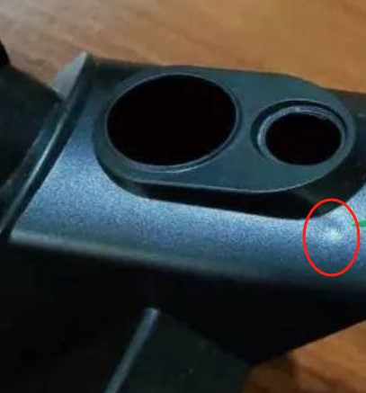
Shrink marks (also known as sink marks) are small, shallow depressions or dimples that appear on the surface of an injection-molded plastic part. They are not cracks or holes, but subtle surface defects caused by uneven cooling and material shrinkage during the molding process. These marks can affect both the appearance and structural integrity of the part, especially in high-precision or cosmetic applications.
Shrink marks are a result of volumetric shrinkage — all thermoplastics shrink as they cool from a molten state to solid. However, the way the material cools and the design of the part can amplify or minimize this natural effect.
Key Causes:
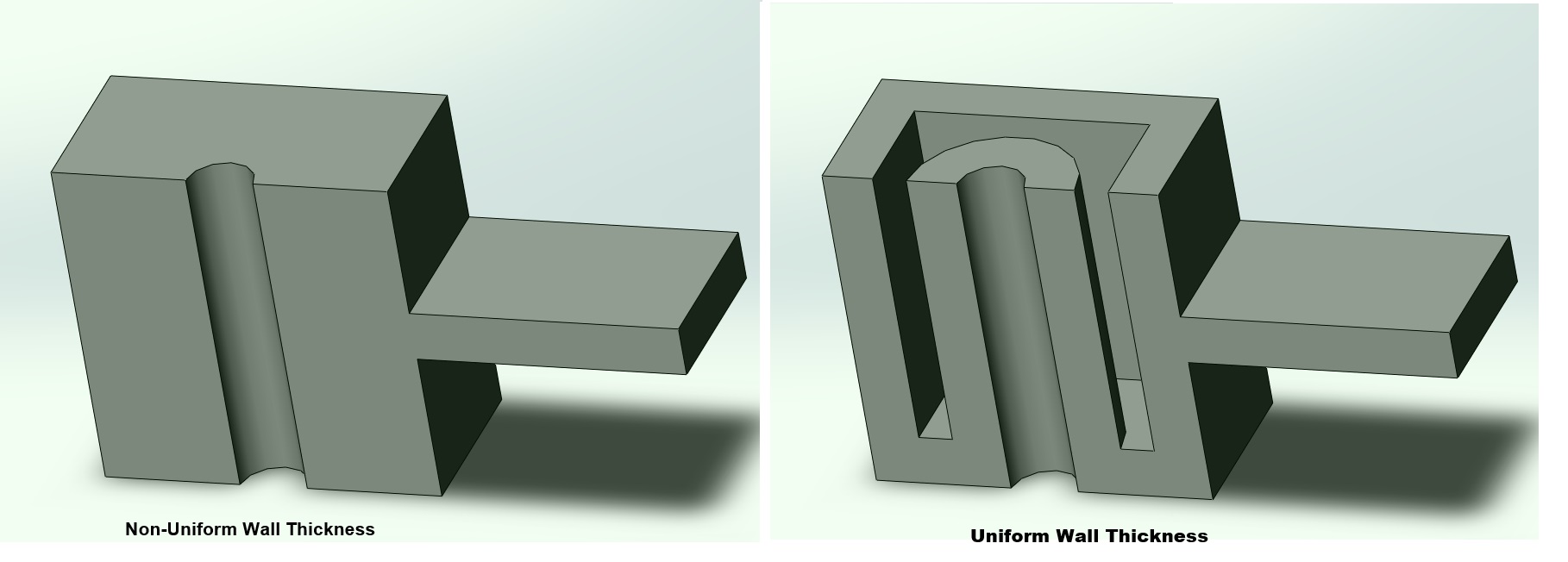
Non-Uniform Wall Thickness
Thicker areas of a part take longer to cool and solidify. As the interior material shrinks, the solidified outer shell can collapse inward, forming a visible dent.
Inadequate Packing Pressure
During the packing phase, molten material is pushed into the mold to compensate for shrinkage. If packing pressure or time is too low, there’s not enough material to maintain the shape, leading to shrink marks.
Material Shrinkage Behavior
Different plastics shrink at different rates. For example, PP and HDPE tend to shrink more than PC or PS, making them more prone to sink marks if not carefully processed.
Improper Gate Design or Location
If the gate is too small, located too far from thicker areas, or freezes too early, the flow of material into critical regions is restricted, reducing packing efficiency.
Insufficient Venting (Indirect Factor)
Poor venting causes trapped air or gas, which resists cavity filling and interferes with packing pressure. In thick sections, this can prevent enough material from reaching the core, increasing the chance of shrink marks.
Shrink marks usually occur on flat or smooth surfaces opposite thick internal features, such as:
Over ribs
Around bosses or mounting posts
Near structural reinforcements
In areas with thicker-than-average wall sections
These internal features act like localized mass concentrations, slowing down the cooling rate and increasing the risk of shrink.
Here are proven design and process strategies to eliminate or reduce shrink marks in molded parts:
Use Uniform Wall Thickness: Aim for consistent wall thickness throughout the part to ensure even cooling.
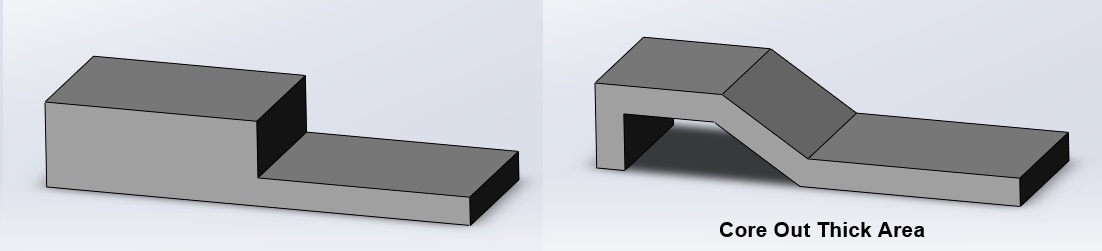
Core Out Thick Sections: Replace solid masses with hollow cores or ribs to reduce shrink-prone volume.
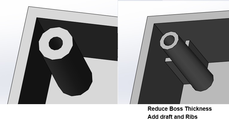
Taper Ribs and Bosses: Use thinner, properly drafted ribs (typically 40–60% of the main wall thickness).
Increase Gate Size or Adjust Location: A larger gate or better gate placement ensures sufficient packing in thicker areas.
Use Multiple Gates: Helps fill large or complex parts more evenly.
Design Proper Vents:
Place vents near thick areas or end-of-fill zones.
Allow trapped air and gases to escape, enabling full cavity fill and proper packing.
Prevent burn marks that could be mistaken for shrink defects.
Increase Packing Pressure and Time: Ensures molten plastic continues to flow into the cavity as the material cools and shrinks.
Optimize Melt and Mold Temperatures: A lower mold temperature may help cool parts more uniformly; however, too cold a mold may freeze the gate too early.
Extend Cooling Time: Allows more uniform internal solidification, reducing stress that leads to sink marks.
Choose materials with lower shrinkage rates or better dimensional stability for cosmetic-critical parts.
Use glass-filled or reinforced materials to minimize overall shrinkage.
At GoodTech MFG Group, we understand that even small surface defects like shrink marks can affect both the functionality and aesthetic appeal of a product. That’s why we use expert part design, advanced mold engineering, and precise process control to deliver parts that meet the highest standards in appearance and performance.


